A true benefit of MPLS technology is the ability to provide Quality of Service (QoS) guarantees over an IP backbone. QoS on an MPLS backbone is used to provide predictable, guaranteed performance metrics required to transport real time and mission-critical traffic. The providers have an overall QoS architecture that is used to deliver a subset of QoS services to each customer. The provider will have multiple classes of service that the customers must align with in order to leverage the providers’ MPLS offering. The providers must have an MPLS QoS architecture that provides end-to-end guarantees for each class of service for each customer. Cisco, for instance, has defined two models that can be used independently or together to provide the end-to-end guarantees for each customer. Cisco defines these as the point-to-cloud and point-to-point models.

The point-to-cloud or “hose” model allows the provider to provision an ingress committed rate (ICR) and egress committed rate (ECR) for each VPN. The ICR and ECR dictate how much bandwidth is allowed to enter and exit the service provider backbone within a VPN. The best way to describe the scenario is with an example. Let’s say we have a VPN with four sites. Each of these sites can communicate with any of the other sites, forming an any-to-any mesh. The sites are labeled “Site 1” through “Site 4.” I will use Site 1 as the basis for discussion. The ICR can be set to only allow Site 1 to inject 50Mbps of traffic into the cloud. This traffic can be destined to any of the other three sites. The ECR can be set to only allow 30Mbps traffic to exit the cloud to Site 1 from the other three sites. These parameters can be set for each class of service. The provider’s backbone will provide bandwidth and delay guarantees for the traffic thresholds as configured for the ICR and ECR. This model allows the provider’s QoS to be transparent to the customer. The customer can dictate the amount of traffic that is sent to each of the provider’s classes of service. The customer does not have to match the provider’s classifications and the customer markings are preserved.

The point-to-point or “pipe” model allows the provider to build virtual QoS pipes between the customer edge routers that are used to provide bandwidth and delay guarantees. This is analogous to legacy ATM and Frame Relay PVC meshings. However, the provider is responsible for the virtual mesh. Once the virtual QoS tunnels are established the provider can offer traffic engineering across the virtual mesh. Each tunnel would have its own QoS characteristics so that the CE-to-CE QoS guarantees are established prior to transmission of data. This is a more granular approach to QoS and adds complexity to the provider’s configuration. The pipe model is not as scalable as the hose model as it requires CE-to-CE pipes for each customer. (From MPLS QoS models by Robbie Harrell)

Best practices for MPLS interoperability of customer QoS with provider QoS

When planning an internal QoS architecture that will utilize an MPLS VPN as the WAN backbone, it is beneficial to consider the provider’s architecture. Service providers have enabled QoS with their MPLS VPN services. This allows the provider to offer multiple classes of service with SLA guarantees. The service provider’s QoS architecture dictates how a customer’s applications are serviced over their backbones. It doesn’t matter what your QoS architecture is, it will have to be modified to match the provider’s ability to deliver within their service parameters. The reality is that the provider has one QoS architecture and the customers can have many different ones. The provider is not going to adapt their architecture to the client’s — therefore it makes sense to understand what the providers offer before engaging in an internal QoS plan.

  • Most providers support only three or four classes of service. Some provide five classes of service, but the majority fall into the first group. Limit your number of classes of traffic to 3-4. You can put any applications you want into these three or four classes, the provider doesn’t care. They will tell you what the performance guarantees are for each class. It is up to you to decide which applications require what guarantees.
  • Providers use DSCP for classification and marking. In most cases when you deploy a MPLS VPN WAN, you will need to classify and mark your QoS traffic before you hand it off to the provider. Some providers offer managed services and they will handle the edge router configurations, others provide templates. The customer is responsible for identifying important traffic and initiating a classification scheme. Use DSCP markings rather than IP precedence at the WAN router edge. Most providers follow some form of assured forwarding markings for their classes and you can easily match the providers. If you don’t know the provider’s markings beforehand, use the DSCP standards. (FromMPLS: Interoperability of customer QoS with provider QoS by Robbie Harrell)


Using MPLS with VoIP  Back to top ↑

Meeting QoS guarantees that ensure reliable voice transmissions can be the biggest challenge of deploying voice over IP (VoIP) traffic. Implementing MPLS can help enterprises rise to that challenge because the protocol offers network engineers a great deal of flexibility and the ability to send voice and data traffic around link failures, congestion and bottlenecks.

MPLS is useful as an enabler for VoIP because it provides ATM-like capabilities with an IP network. Unlike the expensive ATM links that would be required to support VoIP, MPLS provides guaranteed services utilizing IP quality of service on the carrier’s backbone. This service and the ability to converge VoIP onto the data network present a tremendous opportunity to reduce operational costs and consolidate infrastructures.

Real-time services are application services that are susceptible to delay, packet loss and jitter. VoIP and video over IP are considered real-time applications. While other applications such as SAP are vulnerable to delay, VoIP and video over IP (with corresponding voice) are the real focus, because if you cannot deliver these applications with a high degree of confidence that the packets will not be dropped, experience delay or jitter, then you cannot deploy these application services. (From Carrier MPLS support for VoIP by Robbie Harrell)

Before VoIP came along few companies ever created a full mesh because there was a cost associated with each permanent virtual circuit (PVC). Instead, companies required traffic in a hub-and-spoke topology to pass from one remote office to another through the hub site, using both its inbound and outbound bandwidth. This was generally OK, because one remote office never talked to another before VoIP.


However, packets don’t fly directly between any two sites. In reality, your packets are probably riding some good old-fashioned frame-relay or ATM network to get from your office to your carrier’s closest MPLS POP. As someone with a keen interest in low-latency, you’ll want to ask some pointed questions about where the MPLS POP actually is located and what the Layer 2 path to get there looks like, because your packets could be taking a scenic route that won’t show up on traceroutes.

Another significant difference between PVCs and MPLS is that the technology really provides no mechanical equivalent of committed information rate (CIR), Committed Burst Size (BC) or Excess Burst Size (BE), etc. However, your WAN provider may like those concepts so much that it tries to replicate the functionality with some truly bizarre policing and remarking configurations. Make sure you understand how they’ve implemented QoS and exactly how they treat your packets that exceed the committed data rate (CDR) and what the thresholds are.

Finally, while it was possible for a provisioned PVC or SVC to change its path through the carrier’s backbone, it’s much more likely to actually happen with traffic-engineered paths in MPLS. You should keep track of how much delay your circuits have, and if you see this number suddenly and mysteriously change, there’s a good chance your packets are taking a different path as a result of a failure or the availability of a better path. (From MPLS — what voice managers need to know by Tom Lancaster)
Scenario#41 – Mailbox in use

Posted: September 29, 2012 in Uncategorized

A customer reported an issue regarding a user where if she tried to listen to her voicemail messages she would get “Mailbox is in use”.

This issue normally happens if any TUI session or VoiceView sessions are open in any other phones having access to that GDM or the ports have become stuck or busy.
To resolve the issue, login to CLI of CUE module and issue this command:

voicemail mailbox unlock owner Natasha

OR

voicemail mailbox unlock telephonenumber 6311


View original post

Good stuff Here for sure.

One of our customer reported an issue with ring back tone when calling their Contact center.

I made a test call and observed that as a caller when you call their main Contact center number all you hear is dead silence and then when agent picks up the phone you could hear them talk. There was no ring back tone and no automated messages before an agent picks up the call.

The call flow was something like this:

PSTN > ISDN30 > H323 Dial-peer > SIP Trunk > 3rd-party Contact Center Equipment

First I thought it could be the third-party equipment which was not sending back the ring back tone so I asked them to confirm this. They came back saying they are definitely sending ring back and there was no issue with their equipment.

Looking at Q931 debugs I could see ALERTING message with payload but wasn’t sure why…

View original post 708 more words

One of the more tedious parts of any phone system deployment is configuring the access layer switches to support said phones.  The configuration in and of itself isn’t complicated, but every port that may receive a phone needs to be setup correctly.  In Cisco parlance, this is accomplished with the switchport voice vlan <ID> command.  I’ve typed that into the CLI a thousand times and never really knew what it did besides “make the phones work”.  After a little research, I finally found some answers.  I thought I’d share them with you.

In the old days, before the Catalyst 2950, configuring a switch port for use by a phone involved creating an explicit 802.1q trunk.  This made sense from the perspective that it allowed traffic from multiple VLANs to pass on a single link.  It also allowed the 802.1p priority bits for Quality of Service (QoS) tagging to be sent with the frames.  The downside is that it was very difficult for phone mobility.  You either needed to provision every phone-facing switchport in your organization to be an 802.1q trunk or you had to leave the phones were they were.  While the latter is usually the case in most of my deployments, the mobility provided by the ability to plug a phone in anywhere in the network and not worry about extra configuration is key to some clients.  Thankfully, Cisco fixed this starting in the 2950 with a little concept known as the Auxiliary VLAN.

The Auxiliary VLAN (AUX VLAN) is a specialized VLAN that sits beside a regular access VLAN configured on a switch (sometimes called a “normal” VLAN).  The purpose of the AUX VLAN is to allow IP phones to transmit their payloads along with the untagged data coming from a PC that might be plugged into a switchport on the back of the phone.  The AUX VLAN allows these two devices to transmit on the same port without the need to use an explicit trunk on the link.  In addition, since the port is not configured explicitly as an 802.1q trunk, extraneous VLANs will not be flooded over the port.  In essence, the port becomes a two VLAN trunk.  All the phone traffic is tagged with the ID of the AUX VLAN and the PC traffic is untagged.  Curiously, according to this document, the traffic in the AUX VLAN must also carry a Class of Service (CoS) of 5 along with the AUX VLAN ID.  Otherwise, the traffic is dropped.  So how does the phone get the ID of the AUX VLAN so it can start sending the traffic?  Ah, that’s where CDP comes in.

Cisco Discovery Protocol (CDP) is very crucial in the operation of a Cisco IP phone.  It not only provides the AUX (Voice) VLAN ID for the phone to being sending traffic on the AUX VLAN, it also allows the phone to automatically negotiate power settings.  This allows the phone to use less than the maximum 15.4 watts of power under the 802.3af PoE standard.  If you disable CDP on the port facing the phone/PC you will likely start pulling your hair out.  Even though the phone might have already assigned itself in the Voice VLAN, removing CDP from the switchport in question causes it to forget where to find the voice VLAN.  You’ll need to re-enable CDP and reboot the phone.  You could also statically configure an 802.1q trunk to fix the issue, but where’s the fun in that?

One other curious note is that I’ve always been told that the connection between the phone and the switch when switchport voice vlan is configured is a “special 802.1q trunk”.  Not that I’ve ever been able to see that configuration, as show interface trunk seems to think that the port isn’t trunking and show interface switchport says that it’s an access port.  The key is in Cisco’s documentation.  The correct term for a port with switchport voice vlan configured is a “multi-VLAN access port”.  The distinction between the two is that only the two vlans (voice and access) configured on the switchport will be accepted on the link.  If you were to do something silly like, oh I don’t know, plug another switch into the back of the phone and configure an access port on that switch to be in a different VLAN than the voice or PC access VLAN, traffic will not pass through the phone port to the switch.  Once again, that’s because this isn’t a real trunk.  The switch will only accept tagged frames from the Voice (AUX) VLAN.

Thanks Networking Nerd for this article.


On CUPC > Help > Show Server Health, sometimes you would see failed items with the message “invalid credential”, such as “Presence”, “Desk Phone”, or “Voicemail”.

This is very confusing. Since you already logged into CUPC, why it’s giving you “invalid credential”? What kind of credential it was failing on?

Before we can move further, please take a look at “CUPS and CUPC, father and son? or not“.

CUPS and CUPC’s relationship is not as tight as you thought. CUPC has many features, but CUPS is only relevant in two of them (configuration repository and presence).

When you type username and password on CUPC login window, that is majorly for “Configuration Repository”. If you typed in the wrong password, CUPC won’t be able to download configuration from CUPS. No other functions CUPC can perform without configuration.

However, sucessfully downloading configuration does not guarantee other functionalities. To use other fucntions, a 2nd authentication might be required (either explicitly or implicitly).

Presence – Invalid Credential

For presence feature, 2nd authentication is required on SIP layer. This authentication is implicit. For more details on “Digest Authentication”, please see http://www.ietf.org/rfc/rfc3261.txt.

Why is it implicit? Why does it fail?

To make it implicit is Cisco development’s decision. If they made it explicit, you’d have to provide digest credential (2nd password) after login. This could be annoying since SSO (Single Sign On) was what we preferred.

So Cisco development made CUPS/CUPC worked this way:
1) You (system admin) configure digest credential on CUCM Admin > User Management > End User page.
2) CUPS synchronizes digest credentials from CUCM to CUPS.
3) CUPS transmits digest credential to CUPC during logon.
4) CUPC uses that degest credential to authenticate with SIP proxy.

Step 3 and 4 look funny because it’s like a door keeper gives the key to you and asks you open the door with the key. But keep in mind:
a) The “door keeper” acutally verified your identify (username/password), before giving you the key.
b) The key was encrypted during transmission.
c) The key door keeper gave you might be for a different door (SIP proxy could be on a different server other than the logon server)
d) This is a compromise (or balance) between inconvenience of SSO and SIP protocol requirements.

If there’s no digest credential configured on CUCM (ie. it’s blank), you’ll get “Invalid Credential” for presence. To fix it, take one of the following options:

Option 1: Go to CUCM Admin > User Management > End User, configure a dummy value for “digest credential”. It could be any value. Why? See workflow explained above.

Option 2: Go to CUPS Admin > Cisco Unified Presence > Proxy Server > Incoming ACL. (on CUPS 7.x, it’s “System > Security > Incoming ACL”. Configure an address pattern that covers your CUPC machines. For example, a “all” pattern matches all machines.

This option is considered less secure, because any machine in that address pattern (subnet) would be able to connect to SIP proxy without digest authentication challenge.

Option 3: Go to System > Service Parameters > Cisco UP SIP Proxy. Set “Authentication Module” to “off”. This is the least secure option, which turns off SIP authentication at all.

Desk Phone – Invalid Credential

This usually happens when CUCM was configured to use “LDAP Authentication”.

To control desk phone from CUPC, CTI protocol was used. Before a CTI client (CUPC) can control the phone, it needs to authenticate with CTI server (CTIManager). This authentication is implicit. CUPC would use the same logon username/password to authenticate with CTIManager. CTIManager, in turn, would authenticate that with LDAP.

Question: Why the authentication would fail?
Answer: In short, this is a bug on CUCM.

Question: Any workaround for that before we can upgrade CUCM?
Answer: On CUCM, change LDAP authentication port to 3268 and restart CTIManager.

Question: Why it would fix the problem?
Answer: When LDAP referral happens, CTIManager would fail on authentication. Using 3268 (Global Catalog) port eliminate LDAP referals.

Question: Why it only affects CUPC?
Answer: CUPC is the only application (so far) that uses end user credential to authenticate with CTIManager.

Voicemail – Invalid username/password or account locked

Depending on what Unity edition you’re running (Unity or Unity Connection), the cause could be different.

Before moving on, please take a look at “How to test IMAP connection“.

On Exchange 2007, it’s because IMAP login was disabled on TCP (port 143) by default.

On Unity Connection, make sure you reset “Web Application Password” instead of VoiceMail password.

 (R) 2012

So working on a huge refresh project where license issues are for sure going to become an issue. So I should start now on discovering more on Cisco’s Licensing which I did and I can say it is another mysterious area in Unified Communication. Each product has its own licensing model.

So let me share what I found:
CUCM (CallManager)

CUCM license resides on publisher. The ‘host ID’ in license file needs to match the MAC address of the publisher.

There are three different types of license for CUCM: node license, feature license and device license (DLU). Node license is for server node. Feature license is required for upgrade or CUCM 7 and above. Device license is required to configure devices (such as phones).

CER (Emergency Responder or e911)

CER license resides on publisher and subscriber (if you have CER subscriber). License file on pub needs to match the MAC address of pub. License file on sub needs to match the MAC address of sub.

If you received a “license expired” message on a two-node CER deployment, 99% of the chance you don’t have a license for sub (wrong MAC address).

CUPS (Presence)

Like CUCM, CUPS also has node license and device license. Node license resides on CUPS publisher. Device license resides on CUCM (it’s just a regular DLU license).

Node license could contain proxy or PE (Presence Engine) or both.

I will continue to update this post with more information as I continue to discover it.. Let’s hope it is not in a “Lessons Learned” scenario..


(R) 2012

Wow, am I old or is Cisco moving at about 3 revisions a year? I think the first was correct.. Oh well. I have a huge 8.x project coming up for a client and so I have been installing a lab version to play around with. Last night I tried to MAP my lab UC appliance from a Windows machine, then I remember that this changed as of CCM 5.x….

So I’m sure you remember the “good old days” of CCM 4.x? You can do almost everything on the box. Because it’s in fact a Windows 2000 box. However, this brings security and supportability issues.

With the introduction of Linux-based Unified Communication appliance (CUCM 5.x – 8.x), Cisco locked down the box. You can only access the box via admin web page or a tailored command line.

One of the inconveniences is to review log files. On the old-school CCM 4.x, you may just view the logs in C:\Program Files\Cisco\Trace. On the new UC appliance, you’ll have to use RTMT (RealTime Monitoring Tool). This is especially annoying if you’re testing your system. For each test, you’ll have to download a new set of logs to your computer. (though you may use ‘Remote Browse’ in RTMT, its function is very limited)

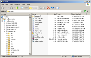
What if we can go back to the “good old days” and view the file system just like a Windows drive? I think I discovered a way to do it on a forum site.

Take a look at the screenshot below. It’s a CUCM 6.1.4 mapped to my Windows XP laptop. You can read/write files on CUCM just like a local hard drive. For those people who are not a fan of VI, you may use your favorite editor (such as Notepad++/UltraEdit). And you may use any Windows tools, such as Windows search, WinGrep, WinZip, etc. How’s that? 🙂

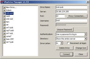
To achieve this, you need two things: a root account on CUCM and a software who can map a SFTP server to a network drive (such as sFTPdrive).

 BAM issue solved. In closing I must admit, I was one of the Cisco CCVP’s at Cisco Live asking developers WHEN ARE YOU GOING TO STOP USING WINDOWS? – Soon my friend, soon.. So I would trade this inconvenience any day to keep from having to deal with Microsoft.

Modify Cisco License MAC

Posted: May 24, 2012 in Cisco CallManager, CUCM
Tags: , , ,

Cisco used to bind license file to physical MAC address.  Now, it moves to “License MAC”, which is a hash value of multiple system parameters such as NIC speed, NTP, DNS, hostname, etc.

To view the license MAC, you need to install the system first (CUCM, UCCX, CUPS, etc.).  Then use the “show status” command.

This is somehow inconvenient:

1) You cannot get the license file before finishing the installation.

I personally prefer to get everything ready before starting the installation, such as IP address, hostname, password, license file, installation media, etc.  You could run into lots of surprises when trying to get the license file.

2) When the system parameter was changed, the license file yield invalid.

For example, you add/change DNS server settings on the system, which is pretty common during system integration.

It would be better if you could dictate what license MAC the system use.  You may also use some schema like: AABBCCDDEEFF, where AA is the product code, BB is the site code, CC is the node number, DD is the version number, etc.

In the example above, the “License MAC” was changed to “abcdef123456”.

Since you can use whatever License MAC you like, you may:

  • Get the license file before the system was installed
  • Keep using the same license file after system parameters was changed (such as DNS)

To specify the license MAC, you need to have root access to the system.  Then you’ll modify the file /usr/local/bin/base_scripts/LicenseMac.sh.  To the bottom of the file, replace the line

FinalString=`expr substr “$SHA1sum” 1 12`

to

FinalString=”abcdef123456″

In newer versions, you might have to change the /etc/selinux/config file so that selinux runs in permissive mode.
Reminder: Don’t be evil.  😉 – and be sure to pay it forward!!!
(R) 2012

Cisco 642-416 Test Prep

Posted: May 22, 2012 in Training
Tags: , ,

The determining factor for whether a gateway registers with a TYPE of VOIP-GW or H323-GW relies entirely on the “allow-connections” commands entered under “voice service voip.” Essentially, if your gateway is functioning as an IP-to-IP gateway, it will display H323-GW.

The commands that make or break this:

voice service voip
allow-connections h t h
allow-connections h t s
allow-connections s t h
allow-connections s t s

After adding or removing these, make sure to bounce your gateway registration with the gatekeeper using “no gateway” and “gateway.”

I just verified this. Here is a snapshot without the commands listed above:

HQ-RTR#show gatekeeper endpoints
GATEKEEPER ENDPOINT REGISTRATION
================================
CallSignalAddr Port RASSignalAddr Port Zone Name Type Flags
————— —– ————— —– ——— —- —–
10.10.202.1 1720 10.10.202.1 58978 Spain VOIP-GW
H323-ID: BR2-RTR
Voice Capacity Max.= Avail.= Current.= 0

After adding the commands listed above:

HQ-RTR#show gatekeeper endpoints
GATEKEEPER ENDPOINT REGISTRATION
================================
CallSignalAddr Port RASSignalAddr Port Zone Name Type Flags
————— —– ————— —– ——— —- —–
10.10.202.1 1720 10.10.202.1 50555 Spain H323-GW
H323-ID: BR2-RTR
Voice Capacity Max.= Avail.= Current.= 0